
- #SERVO MOTOR ARDUINO CONNECTION INSTALL#
- #SERVO MOTOR ARDUINO CONNECTION CODE#
- #SERVO MOTOR ARDUINO CONNECTION PC#
As result, the servo will continuously move clockwise and counterclockwise. For this code, the home position is zero degrees while 180 is the final position. When the motor has completed a 180-degree rotation, it will proceed to revolve in the inverse direction until it reaches the home position. The servo motor will spin gently from 0 to 180 degrees, one degree at a time, when the program starts. This clockwise and counterclockwise scenario continues. Firstly, it moves clockwise until reaches 180 degrees, while then moves counterclockwise to reach zero degrees. The write(pos) line will manage the PWM modulation in order to get the required degrees position.įor every step, there is a wait for 15 milliseconds (s) so that it should reach that step. The variable ‘pos’ defines the required servo’s position. In the loop section, we create (as test) a continuous sweep from 0 to 180 degrees in steps of 1 degree. Here, 500 is the pulse width applied to the servo signal pin to reach zero degrees and 2500 matches the 180 degrees. Its other pins are power supply pins and are connected to 5V and GND (Red and Brown). Pin D5 of NodeMCU will provide the necessary PWM signal to the Servo (Orange).

connecting ESP8266 to WiFi, getting information from Web and finally controlling the Servo. In the setup section, we define the pin where the servo signal is connected as the first variable in the attach function, containing “(9, 500, 2500)”. The main program responsible for everything i.e. We create a servo object with the name servo_9. We start adding the library for the servo and the initial position (which is zero). Please get the zip files from the following link or add them from the available libraries in your Arduino IDE. The servo is wired exactly as in the Sweep example, but this time you need extra connections to 5V and GND for the potentiometer, so you must use a breadboard. The ground wire is typically black or brown and should be connected to a ground pin on the board. The power wire is typically red, and should be connected to the 5V pin on the Arduino board.
#SERVO MOTOR ARDUINO CONNECTION INSTALL#
You also need to install the following library, according to my Install Arduino Libraries: methods to add libraries with Arduino IDE tutorial. Servo Motor 10k ohm potentiometer hook-up wires Circuit Servo motors have three wires: power, ground, and signal.
#SERVO MOTOR ARDUINO CONNECTION CODE#
ino code and libraries from my download area with the following link:
#SERVO MOTOR ARDUINO CONNECTION PC#
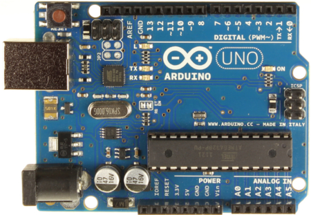
For the very first steps, you can refer to Connecting Windows PC with Arduino tutorial. You can get the. Please follow the wiring that presents in the picture, according to Arduino Uno Pinout: Sr.Ĭonnections Pins Get the Servo code and LibraryĬonnect your PC to Arduino and open Arduino IDE. As shown in the image below, the module connects with Arduino Uno. Because of the position of the servo control through the duty cycle of the pulse. The signal pin must connect to any pulse width modulation (PWM) pin of the Arduino Uno. There are 3 pins of the servo motor, VCC connects to the +5V, Ground Connect with the GND and Signal connects with the pin 9 of the Arduino Uno. Step-by-Step Procedure Wiring Diagram of Servo with Arduino


 0 kommentar(er)
